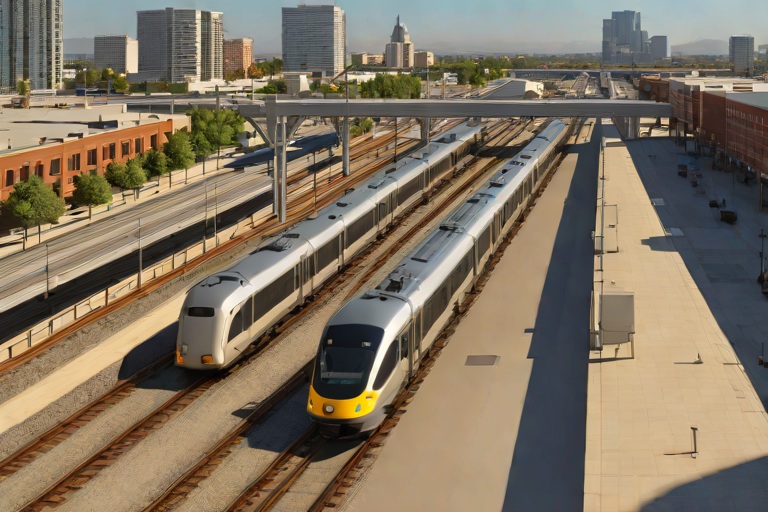
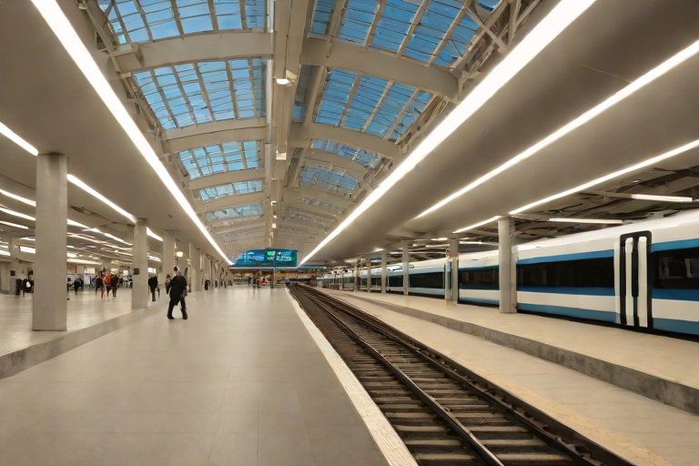
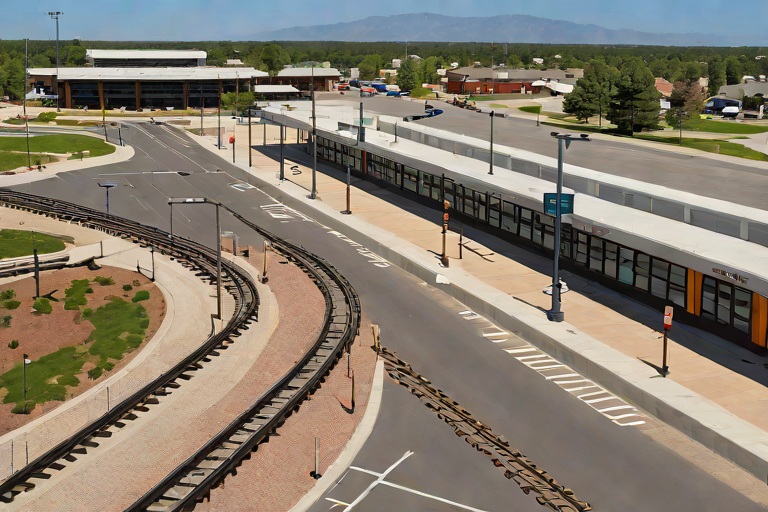
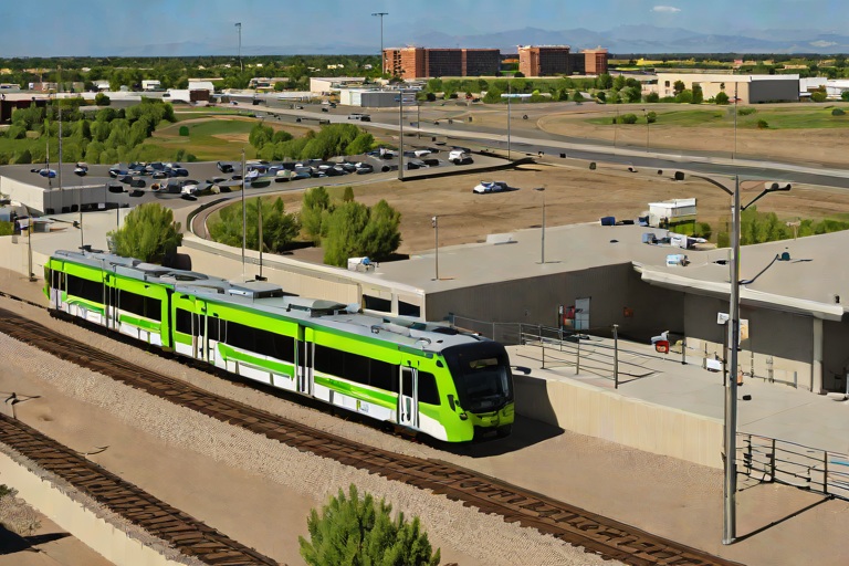
Overhead Catenary Wire Tensioning & Thermal Sag Mitigation across the Union Station Transit Hub
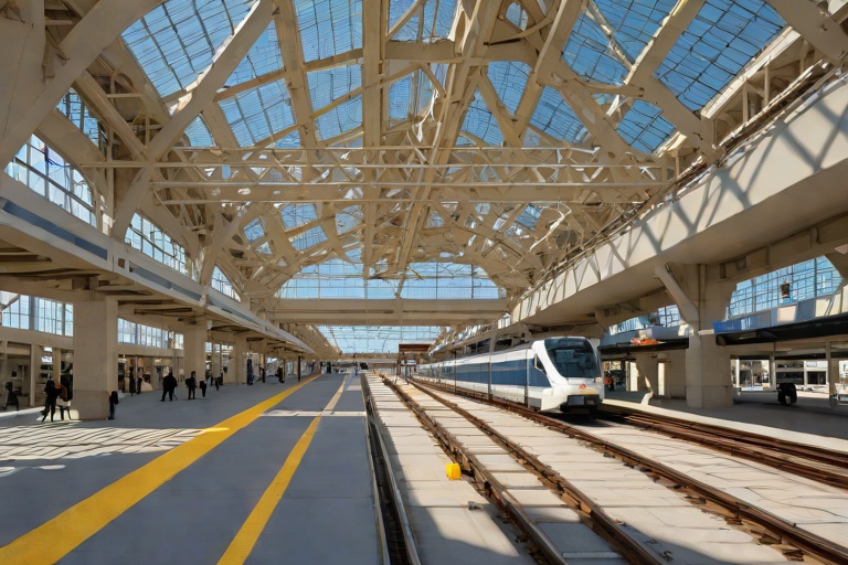
Mechanical Equilibrium and Tensioning Architecture
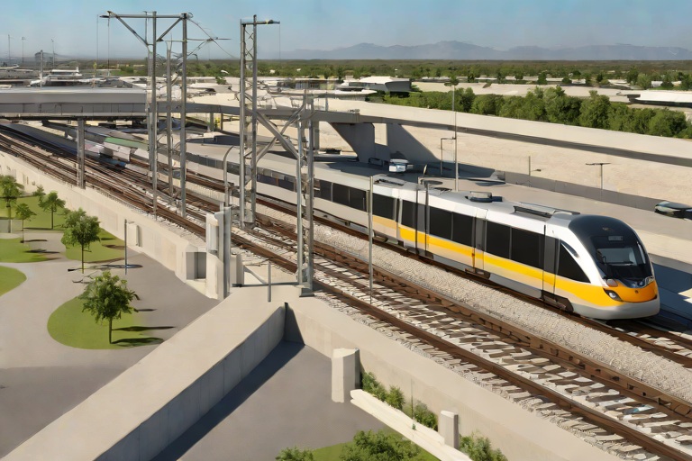
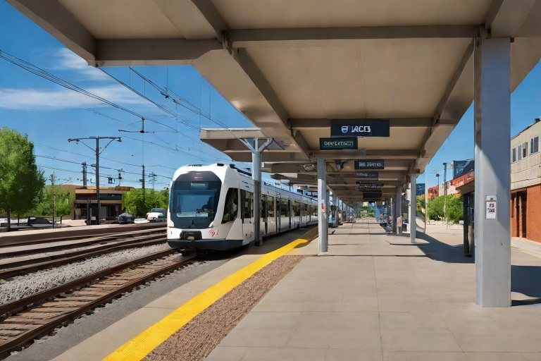
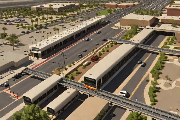
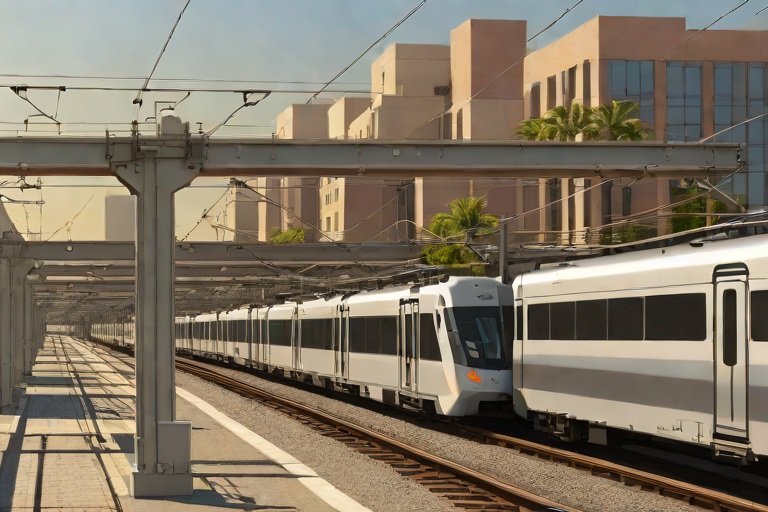
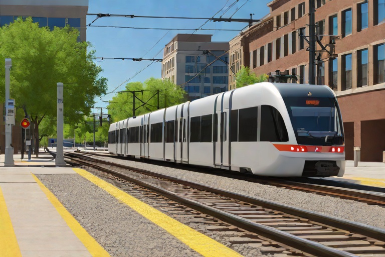
The overhead catenary system (OCS) within a high-traffic environment like the Union Station Transit Hub operates as a complex balancing act between tensile force and gravitational load. At its core, the system relies on a two-wire configuration: the messenger wire, which provides the primary structural support, and the contact wire, which delivers electrical power to the rolling stock. The mechanical equilibrium is maintained through the precise application of tension, ensuring that the contact wire remains sufficiently level to prevent pantograph bounce or catastrophic entanglement.
To achieve this stability, engineering specifications dictate the use of Constant Tensioning Devices (CTDs), typically utilizing a balance-weight system or heavy-duty spring assemblies. These devices counteract the inherent elasticity of the copper alloys used in the wiring. Without active tensioning, the contact wire would exhibit excessive vertical displacement, leading to uneven wear on the pantograph carbon strips and potential arcing. The tensioning architecture must account for the "catenary constant," a mathematical relationship between the wire's weight per unit length and the horizontal tension applied.
- Balance Weight Assemblies: These utilize gravity to maintain a constant pull on the wire regardless of length changes, ensuring the tension remains within the narrow operational window of 10kN to 20kN.
- Dropper Optimization: The vertical wires connecting the messenger to the contact wire are spaced according to specific parabolic curves to minimize the "sag" of the contact wire.
- Elasticity Coefficients: Selection of hard-drawn copper or cadmium-copper alloys to minimize permanent elongation under high tensile loads.
- Anchor Point Integrity: The use of high-strength steel brackets bolted to the primary structural steel of the hub to prevent creep at the termination points.
Thermal Expansion Dynamics and Sag Analysis
Thermal volatility represents the primary threat to the geometric stability of the catenary system. Copper, the primary material for OCS, possesses a significant coefficient of linear thermal expansion (CLTE). In a transit hub that bridges the gap between climate-controlled interior concourses and exposed exterior platforms, the temperature gradient can be extreme. As the ambient temperature rises, the wire expands, increasing the length of the span and resulting in "thermal sag." Conversely, extreme cold causes the wire to contract, increasing the tensile stress on the support brackets and risking a "hard-pull" failure at the anchor points.
The forensic analysis of thermal sag involves calculating the Delta T (change in temperature) and its direct impact on the wire's vertical profile. If the sag exceeds the maximum allowable tolerance—typically measured in millimeters relative to the rail head—the risk of a "dewirement" increases. This occurs when the pantograph rises above the contact wire during a high-speed transition, potentially tearing down several spans of the OCS. The interaction between the thermal expansion of the wire and the thermal expansion of the supporting steel roof structure creates a secondary set of stresses that must be modeled using finite element analysis.
- Linear Expansion Rates: Calculating the millimeter-per-meter expansion of copper over spans exceeding 100 meters.
- Sag-Tension Curves: Utilizing empirical data to map the relationship between temperature fluctuations and the vertical displacement of the contact wire.
- Heat Sink Effects: Analyzing how the thermal mass of the station's concrete and steel roof influences the cooling and heating cycles of the wires.
- Critical Temperature Thresholds: Identifying the specific Celsius points where tensioning weights reach their maximum travel limit.
Structural Interface and Envelope Load Distribution
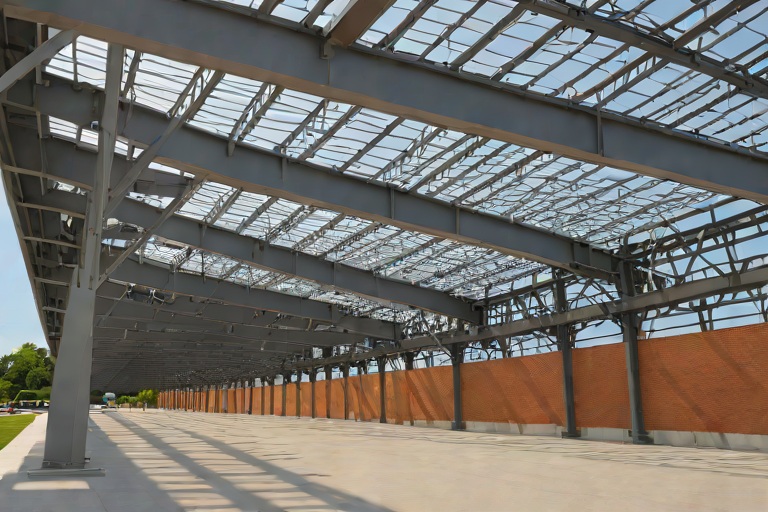
From a building envelope and forensics perspective, the catenary system does not exist in isolation; it is an integrated load on the station's roofing and support infrastructure. The tensioning devices exert massive horizontal forces on the roof trusses. If these loads are not properly distributed, they can lead to structural deformation of the roof decking or the compromise of the waterproofing membrane. Forensic inspections often reveal shear stress at the points where the catenary supports penetrate the building envelope, leading to micro-cracks in the concrete or fatigue in the steel fasteners.
The interface between the OCS and the roof requires rigorous galvanic isolation to prevent bimetallic corrosion. Because the catenary wires carry high-voltage current and the roof structure is grounded, any failure in the insulation brackets can lead to stray current leakage. This not only poses a safety risk but also accelerates the corrosion of the roof's structural members. Furthermore, the vibration induced by passing trains is transmitted through the wires into the roof structure, necessitating the use of vibration-dampening mounts to prevent the loosening of fasteners over time.
- Shear Force Analysis: Evaluating the lateral load on roof beams caused by the tensioning of the messenger wire.
- Galvanic Isolation: Implementing neoprene or high-density polymer insulators to separate the electrical system from the building's steel frame.
- Fastener Fatigue: Monitoring the bolt-torque specifications of the anchor brackets to prevent vibration-induced backing out.
- Envelope Penetration Sealing: Utilizing high-performance flashing and sealant systems to ensure that OCS support points do not become ingress points for moisture.
Mitigation Frameworks and Lifecycle Maintenance
Mitigating thermal sag and tensioning failure requires a transition from reactive maintenance to a predictive, data-driven framework. The implementation of automated tensioning systems, which utilize hydraulic or pneumatic actuators instead of simple weights, allows for real-time adjustments based on sensor data. These systems can automatically compensate for temperature swings, maintaining a precise wire height regardless of the external environment. Additionally, the use of laser-based monitoring systems provides a continuous profile of the wire's height, alerting engineers to sag anomalies before they reach critical thresholds.
Long-term lifecycle management focuses on the mitigation of "creep," the
Aquashield Roofing Corporation
4006 Morris Ct.
Chesapeake, VA 23323
Direct Line: 757-553-5191
GPS Coordinates: 36.755164, -76.353932
Virginia Beach Roofing Company - Roofing Service Virginia Beach VA, Roofing Contractor
585 S Birdneck Rd #106
Virginia Beach, VA 23451
Direct Line: +17576318100
Google Maps Plus Code: RXCX+V7 Virginia Beach, Virginia
GPS Coordinates: 36.822156, -76.001565